Water Supply & ISO
Outline:
- ISO
- ISO Classification
- Divergence
- Water Delivery Supply Requirements
- Types of Water Supply
- Presurized System
- Suction Supply
- Fire Department Supply
- Tanker Supply
- Large Diameter Hose Lay
- Combination of a & b
There is an old saying:
Where there is life . . . . . . there is water”
The trick is to figure out how to make it usable for fighting fires and ideally while you accomplish this, do it in such a way it will count toward lowering your ISO Classification.
A. ISO
The Insurance Services Office, Inc. (ISO) is a leading source of information about risk for the property & casualty insurance industry. Its products help customers measure, manage and reduce risk. ISO is used by insurance companies in most states to evaluate fire departments for the purpose of establishing insurance premiums in the local areas. In states using ISO; Fire Alarm, Fire Department, and Water Supply are measured in the Fire Suppression Rating Schedule (FSRS). This schedule reviews the major elements of a community’s fire-suppression system and develops a numerical grading called a Public Protection Classification (PPC). Within this grading there are 10 classifications. A classification of 1 is the best and a classification of 10 would be the worst (having no recognized fire protection).
ISO Classification (PPC)
In obtaining an ISO Classification, the grading is broken down into three major categories. They are:
| Receiving and Handling of Fire Alarms - | 10 % = 10 points |
| Fire Department - | 50 % = 50 points |
| Water Supply - | 40 % = 40 points |
| 100 % = 100 points |
Forty percent of the grading is based on the community's water supply. This part of the survey focuses on whether the community has sufficient water supply for fire suppression beyond maximum daily consumption. For those communities without a municipal water system sufficient for fire suppression, other alternative water supplies will be evaluated. All components of the water supply system will be reviewed to determine your ability to supply adequate quantities throughout your fire protected area.
2. Divergence
One must also understand engine companies and water supply compliment each other. It is very important the 50/40 ratio remain balanced. If one scores better (than the 50/40 ratio) in either of these two categories, ISO will apply what is called “Divergence Points” (negative points) in order to maintain this ratio.
In other words, you could have a brand new engine but if you have very little water to pump with, you may not get full credit for the engine. You are only as effective as the weakest link.
Example:
You grade 40 points on Fire Department but only 10 points on Water
Supply. Divergence points are figured at 50% of your (Credit for
Water Supply) minus 0.8 (Credit for Fire Department). The formula
is:
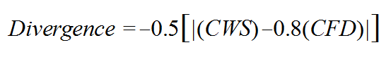
The Divergence in the above example is equal to -11.0 points.
Therefore, the net Credit for Fire Department and Credit for Water
Supply (after Divergence) is 39.0 points.
Again let me stress this 50/40 balance is critical to obtaining a good score and having an effective operation. You do not want to receive any negative "Divergence Points".
Does this mean you should not buy a new engine because you may not get full credit for it? Absolutely not! You should always strive to improve. I am simply pointing out both categories must balance for you to have effective fire suppression capabilities.
3. Water Supply Delivery Requirements
Also reviewed in an ISO grading survey, is the timing of water delivery to the fire scene. A water supply must be established at the rate of 250 gpm within 5 minutes after arrival of the 1st engine to the fire scene. If the rate of flow can be increased within 15 minutes of arrival at the fire scene, and can be continued for the 2 hour duration, the higher rate will be credited. Note however; once flow has started at the 250 gpm flow, you cannot break the flow. This means you must have adequate supply to sustain the 250 gpm between the 5 min start and the 15 min limit. This is equivalent to a minimum of 3,750 gallons. This initial flow may begin from any source; on board water, dump tank, nurse tanker, other engines or by direct connection to a water source.
Note; while actual flows for 2 hours will not be required, you will be required to demonstrate your delivery capability. Sources and delivery verification will be mathematically calculated to validate the 2 hr. requirement for sustained water flow.
B. There are Three Types of Water Supply:
- Pressurized System
- Suction Supply
- Fire Department Supply
When properly supported by engines and meeting all other ISO criteria, any of these sources; having the required capacity and flow, may count toward lowering one's ISO Classification. While ISO always looks at the "worse case scenario" for water supply credit and recognition, one should not overlook water supplies that may be seasonal or small in capacity.
While these marginal supplies will not count toward an ISO Classification or insurance reduction, where practical, it is better to have a water supply that could provide some water than none at all. Having said that, if you do have a source that falls short of ISO criteria it should be clearly marked and everyone should have a clear understanding of its limitations. All pre-fire plans and Automatic Aid Companies should take this into consideration.
1. Pressurized Water System
A pressurized water system is usually thought of as a municipal water system whereby fire hydrants are normally installed on water mains using a grid system. In other words water would arrive at the hydrant from possibly two or more directions. Water in this type of system can be supplied using elevated tanks, pumps, gravity flow or a combination of these systems.
A pressurized system can also be established by installing a dry hydrant utilizing an above grade water source, such as a pond. In this type of installation a valve can be opened permitting water to flow to the dry hydrant head, which in turn is connected to the fire pump. If the system is designed with an air pocket to keep the head dry for freeze protection, some priming will be required in order to facilitate the gravity flow of water.
It is imperative that SOP’s are written and understood for these installations. Automatic Aid Companies should also practice use of these installations as they are usually the ones that will be providing your water supply. I might also note fire departments using Automatic Aid should have quarterly drills together in order to get full credit in the training category. Obviously water supply training would fit well into these exercises.
While pressure is usually low in gravity flow installations, large amounts of water can be obtained. A 6" dia orifice with 23.1 ft of head (= to 10 psi) will flow 3,405 gpm. So, it is easy to see even a few feet of head pressure, using 6" pipe will produce large amounts of water. The key for success is, volume for water supply, pressure for fire attack.
2. Suction Supply
Suction can be established from numerous sources of water.
- Direct from a water source such as ponds, lakes & streams.
- From fixed piping installations such as a dry hydrant.
- From drop tanks utilizing a tanker shuttle system.
A suction supply is obtained when a non-collapsible hose is attached to the intake of a pump and extended into an open water source. Using a primer, pressure inside the pump and hose is lowered below the outside atmospheric air pressure. Atmospheric air pressure (which is based on your elevation above/below sea level) is always being applied to the surface of the water. As the internal pressure in the suction hose is reduced, external pressure then pushes the water up thru the hose into the pump. It works like a drinking straw.
The impeller then catches the water and forces it out thru the discharge lines. Once flow has been established, priming can cease. Remaining small pockets of air can be flushed from inside the system by slowly increasing pump rpms as water is discharged. The amount of flow that can be obtained from a suction supply is influenced by several factors, with "lift" being one of the most important ones.
"Lift" is the distance from the surface of the water source to the intake of the pump. Unlike a pressure supply, "lift" is critical in determining the amount of flow possible from a suction supply.
From a theoretical standpoint one can lift water one atmosphere or 33.9 feet at sea level, however, many other factors enter into the equation during actual draft. Friction loss in the pump, hose and fittings; velocity, water temperature, elevation, lift and internal pump wear, all impact the final outcome or flow of water from any given location. In addition to factors that rob from the starting pressure at a given location, ISO also adds a safety factor, which results in a (maximum allowable lift) of 15 feet. That's less than half of the theoretical lift of 33.9 ft.
While a maximum lift has been established by ISO that does not mean you can always use the full 15 ft. One must also access the needed flow as expressed in gpm's. The Needed Fire Flow (NFF) of a structure is determined by the type of construction, its size, its occupancy and its exposure. It may be necessary to lower the lift a few feet in order to meet the NFF for full credit at that supply point.
Example: In the high mountain elevations of Colorado, it is usually impossible to achieve anything close to the 15 ft lift limitation and still maintain a sizeable flow of water.
Larger suction hose and plumbing as used in a dry hydrant can greatly aid in reducing friction loss, thus increasing flow.
Remember, high lift and/or high elevations are "suction killers", to provide good flow with these handicaps one must reduce friction by all means possible. This may require; reducing run length, increasing pipe diameters, using low angle elbows and cutting strainer losses by increasing the flow area.
For Dry Hydrant installations ETT, L.L.C. has a computer program
that can calculate flow for any given design. This is a free service.
If in doubt call before you dig.
3. Fire Department Supply
There are two types of Fire Department Supplies:
- Tanker Shuttle
- Large Diameter Hose lay
- Combination of A and B.
A fire department supply is that supply delivered to the scene by the fire department. One method of delivery is through the use of tankers. Often referred to as "water on wheels". A second method can be accomplished by laying large diameter hose down the road, creating what is called an "above ground water main". A combination of these two can also be used.
Each of these avenues have certain advantages & disadvantages. One must review manpower, equipment and expense in order to determine what works best for your department. To determine the effectiveness of either operation, ISO will review each component in order to determine your capability for delivery and use of a “fire department supply”.
Some components ISO will review are:
- Pumpers – Pump capacity, pump test records, "on-board" nominal tank size and equipment
- Initial tanker response – Number of tankers, nominal tank size, and time to respond.
- Fill time of tankers
- Dump times of tankers
- Distance for travel from fire station to fire site and from fire site to supply site and return
- Automatic Aid and/or Mutual Aid agreements
- Number of tankers available from surrounding depts. and their nominal tank size.
- Large diameter hose – what length is available? What is the deployment and flow time? Hose diameter?
- Response distance of 2nd engine
Regardless of your choice, ISO will review the overall operation to determine what the weakest link is. Credit will only be given for the amount of water supply that can be sustained by the weakest link.
a. Water shuttle
If the supply is being delivered by tankers the operation should be set up to fill and dump at a minimum of 1,000 gpm. Almost without exception, "fill time" is the weakest link and is the most difficult obstacle to overcome. Travel time, a function of travel distance, can be offset by adding more tankers in the shuttle rotation and dump time can be offset by adding large volume dump valves. Speed of tankers is set by ISO at 35 mph or less.
Before "fill time" can be improved one must first consider from what source and what method, water is being supplied. Is it from a pressurized hydrant or from another pumper at a suction supply? Is the source capable of producing the flow? Remember, in order to deliver 1,000 gpm at the fire scene, you must fill at a higher rate of flow, as you must account for down time due to filler hose connections and disconnections.
Assuming you have a source with sufficient flow, one must next consider how the filler hose is being connected to the tanker. One of the best time savers is the use of quick connects.
Are quick connects being used? Quick connects can cut 30-40 seconds off of the usual required time for threaded connections. Storz and Cam Locks are much faster. I prefer the Cam Locks as they will not untwist and you have handles to hold on to. They are usually less expensive also, as it is a standard gasoline connection used my many companies. They can be adapted directly to a standard hose, thus quickly converting it to a quick connect filler hose.
What size and number of lines are being used?
Two 3" lines usually cut fill time in about half and have much
less friction loss than a 2 ½" hose. Two lines also
work well on low pressure hydrants as they aid in reducing friction
loss.
Special care should be taken to prevent kinks when using low pressure
supplies. Make sure hose lays use large sweeping curves. Avoid kinks.
What is the manpower availability for fill operations? Ideally the driver should never get out of the truck. Personnel should remain at the hydrant ready to leap into action as the tanker arrives. While a 4" hose will rapidly fill a tank, when filled with water it is quite heavy and is very difficult to move. Usually (2) - 3” hoses work best.
How convenient are the connections? Connections should be about waist high. They should be accessible from outside of the vehicle. Opening doors should be avoided. Fill connections work best when they are angled about 30 degrees toward the ground. This helps avoid kinks in the hose, which can kill you if you have low pressure. Connections should never require climbing. Rear lights are a must for night operations.
Are they free flowing or valved? "Check Valves or Up and Over" fill pipes are the quickest. Having to open a valve sometimes causes delays. Valves are stiff, if not lubricated properly and if the line is charged first, the added pressure often makes valves extremely difficult to open. Swinging hinged check valves often tend to leak as the back pressure required to seal them is quite low. Also they tend to swing open with stopping and starting of the truck causing loss. Up and over pipes work the best but they must have a flapper valve on the end of the pipe in the tank to avoid large spills as the truck accelerates or climbs hills.
Are all tanker fill connections set up the same? Again ISO looks at the worse case scenario and "tanker set up" is no exception. If your Automatic Aid tankers are different and require different connections etc. you must account for this during the initial set up or be penalized. If for example you have tankers from different departments that require various connections such as; a Shepard's hook, a Cam Lock, Threaded Fittings and say a fourth that uses Storz. Your initial set up must provide hose with all four connections. Ideally everyone working together should standardize on the same type of connections.
Are hydrant valves used? Another great time saver is the use of hydrant gate valves to control opening and closing of tanker fill lines. Quarter Turn and Gate Valves with speed handles are both possibilities. Regardless of which one is chosen valves should be closed slowly to avoid water hammer. If a pressurized fire hydrant is your source it should be opened up fully and remain full open until the tanker shuttle operation has been completed.
If you are not able to fill at the 1,000 gpm rate you must analyze why. Where is your bottle neck? Start with your source and work your way forward to the fire scene.
b. Large Diameter Hose
For some departments it is more convenient or feasible to use large diameter hose instead of running a tanker shuttle. This method of water supply establishes an above ground water main. Large diameter hose (LDH) is usually found in 4" and 5" sizes. Normally LDH hose comes in 100 ft. sections and has Storz fittings.
A word of caution, if LDH is going to be used and since ISO looks for the weakest link, all engines must be loaded with the same length and size hose. As the same engine is not always the 1st out, this assures the ability to lay LDH regardless of which engine leaves the station first.
The length of LDH allowable is a function of time.
Initially you must be able to have water flowing at the fire scene within 5 minutes after the arrival of the 1st engine. This initial flow may begin from any source; on board water, dump tank, nurse tanker, other engines or by direct connection to a water source. If a long lay of LDH is going to be used to increase the initial flow it must be done within the 15 minute window previously discussed. This would mean you must provide some other source for providing the initial 250 gpm flow for the 15 minute window. In other words if additional time is needed to lay LDH, you must provide the needed flow, up to 3,750 gallons (250 gpm x 15 min) via some other method.
To my knowledge the longest approved run of LDH has been 2,500 feet. If engine 2 is designated as the "water supply" engine, both engines must leave out of the station virtually at the same time to provide maximum hose lay time. Also don’t overlook the time to charge and purge the air from a long lay as this can be quite long.
If this method of water supply is being considered remember, LDH does require special equipment and handling. The time required for the hose lay, charging time & air removal, special hardware & adapters, tools and finally at some point, draining, pickup and loading of the hose must all be taken into consideration. Cost is another factor that cannot be overlooked as all engines must be loaded the same.
For more ISO information regarding water supply, please consult the ISO Fire Suppression Rating Schedule. This publication can be purchased by downloading an order form from the ISO web site www.isomitigation.com or www.iso.com or call them at 800-444-4554.
If I can be of further assistance please call or fax me - toll
free, at
877-827-2797.
Thanks,
Stan Merrett - Owner, ETT, L.L.C.