
Intake Strainers Bridge
Part # 9183-100 (6" only)
Design Usage:
The original "Bridge Strainer".
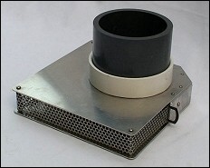 Designed for vertical installation into shallow water from
a bridge or pier. Strainer has a solid top and bottom with inlet
around the 2" outer cumference. The strainer is diamond shaped
to deflect debris and prevent silt buildup which would obstruct
intake of water. The strainer has external eyelet's on each side
providing an anchor point around a post or pier pilling.
Designed for vertical installation into shallow water from
a bridge or pier. Strainer has a solid top and bottom with inlet
around the 2" outer cumference. The strainer is diamond shaped
to deflect debris and prevent silt buildup which would obstruct
intake of water. The strainer has external eyelet's on each side
providing an anchor point around a post or pier pilling.- The Bridge Strainer is designed to be placed with the bottom plate 4"- 6" above the stream bed if needed. It is preferable for this location to be in a flat area of the stream (Not in a depression). The sharp end of the strainer should be pointed downstream and the entire strainer should be located on the downstream side of the pier pilling, if at all possible, for added protection. See diagram for installation techniques.
Pull Down & Flow Rates:
- 100% pull down to the top plate at lower flows. Flows of 1,250 - 1,500 gpm may require 6" - 8" of water above the top plate. Generally the swifter the stream flow the lower the water can be above the strainer plate and still maintain high flow rates.
Material:
- Sheet Aluminum formed for maximum flow and strength.
- Aluminum Wire mesh provides maximum intake.
- SST Screws and Nuts
- 6" Schedule 80 PVC Male coupling designed to glue to 6" Schedule 40 or Schedule 80 PVC pipe. Adapters to SDR 30 also available upon request.
Dimensions:
- Special design is diamond shaped with anchor eyelet's.
- Width at widest point = 12 inches
- Length at longest point = 12 inches
- Thickness at intake = 2 inches
Installation Suggestions:
- If needed consult your local Soil Conservation Department for stream flow data and assistance with figuring drought conditions. In many locations the (RC&D) Resource Conservation and Development group can also be called upon for assistance.
- Before installation severe drought conditions at that specific site should be considered for both location in the stream bed and depth above the bottom. In cases of extreme drought and stream flow, it may be advantageous to build a shallow 1 ft. dam to create a deeper area in which to locate the strainer. In some situations local laws may need to be researched prior to any construction. It is recommended any retainer wall be placed downstream far enough to prevent silt build up around your strainer.
- If possible choose a stream bed location where the bottom is settled. (No Silt)
- If stream flows warrant, attach the strainer on the down side of the pier pilling for added protection from large debris (such as tree trunks and limbs) floating downstream during flooding conditions. The pipe should be attached along it's vertical path for security.
- The strainer is designed so the pipe will glue vertically to the top of the strainer. Final assembly will resemble a shoe or foot. As the vertical pipe terminates at the head it may be advantageous to use a 45 degree head assembly. Make sure, if assembled on a bridge, it does not protrude inside of the railing causing a hazard to traffic. A check with DOT regulations may also be necessary before installation.
- The completed installation should assure that the center line of the strainer is in line with the flow of the stream.
- As a rule of thumb, the bottom plate of the strainer should be above the stream bed by 4 - 6 inches. If you have sufficient stream depth (say 2 ft.) you may wish to increase the clearance slightly.
- If the piping terminates on the stream bank, upon completion of the installation reshape and properly re-seed the bank at the point of entrance to prevent soil erosion. If needed consult your local Soil Conservation Department for assistance in this project.
- The strainer assembly terminates in what is commonly referred
to as a Dry Hydrant head or suction point. There are a variety
of ways in which these can be installed. Most common is the above
ground head, however a flush mount installation is available for
ground installation and works well in many situations. Specific
instructions under "Dry
Hydrant Installations" can also be found on this web
site for your design choice.