
Silt & Mud Solutions
General Information
Silt and Mud present potential wear problems to most pumps and valves. The presence of suspended matter in water may be caused from constant agitation or may be the result of a temporary situation such as a heavy rain. In most cases there will be a clear or clean layer where the water will be of a higher quality. By pulling water from this area you will usually find very little of the suspended particulate. If these conditions exist a Dry Hydrant design should be selected that will allow an intake to be located in this clean or clear zone. In designing these installations one must first determine the type of suspended matter, when is the suspended particulate likely to be present and if a clean layer exists, where it's located.
If no clear area is ever present, it may be necessary to bury the intake in a sand bed. The sand will then act as a filter, preventing the suspended particulate from getting into the water supply. This method can also be used to obtain water in areas of the country where the water table is quite high and the soil is very sandy. Florida and California are some of the areas where this type of intake can be used.
In all cases where you have suspended particulate that is slowly settling to the bottom, the strainer holes should always be installed down. One should also take into account the age of a pond when making a permanent placement of the strainer above the floor. For new ponds install the bottom of the strainer at least three feet above the floor of the pond. This will provide one foot for settlement, which could occur over the next 5 years. Strainers being installed in old established ponds should be installed about 2 feet above the floor.
Warning: For new pond installations one should check frequently for sand and mudslides caused from surface runoff. This can be a huge problem if the watershed area is not properly seeded or landscaped to prevent erosion. Often times one must relocate or dig out around the strainer because of surface water runoff.
They are several ways of placing an intake into the clear zone.
- Supported vertically from the bottom (rigid installation).
- Suspended horizontally from the bottom (adjustable installation).
- Supported vertically from the top (rigid installation).
- Suspended horizontally from the top using flotation buoys.
- Buried intake in a sand bed.
Below are diagrams of these installations. You will note more than one diagram may work for your situation. To select the proper diagram, first make a list of your requirements. Second, match the requirements to the particular design. Third, evaluate each selection from a price and maintenance standpoint before deciding which solution best fits your requirements.
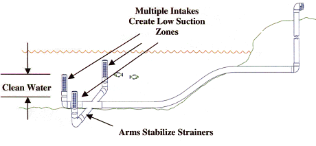
1. Supported vertically from the bottom (rigid installation)
The design shown below uses three Barrel Strainers. These strainers have holes 360 degrees radially around the pipe for a length of 20 inches. Low Level Bridge Strainers turned upside down also work very well and limit the intake zone to an even shorter distance of only a few inches. By using more than one strainer the suction velocity is greatly diminished, thus reducing the chance of suspended debris and weeds being pulled into the strainer.
In addition to providing multiple suction points, the cross arms also act to support the weight of the piping in muddy bottoms and provide good stabilization to the strainers. A "T" fitting can be used if only two strainers are desired. The vertical placement of the strainer will depend on the age of the pond and/or the location of the clean zone. For new ponds allow at least a foot for sediment that may be deposited prior to the pond becoming stable. This process may take up to 5 years.
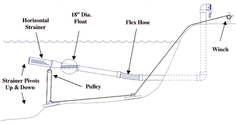
2. Suspended horizontally from the bottom (adjustable installation)
This design utilizes a short piece of flex hose and a floatation buoy installed around the suction pipe. The buoyancy of the float device will try to float the strainer, but is restrained by a SST Cable anchored in concrete on the bottom of the water supply.
This design may be used in river areas where flooding, heavy debris or other changing factors enter into the picture. The design also provides a means of raising the strainer for inspection. This design also can be used to prevent boating hazards.
The cable follows the contour of the bottom, and can be attached to a simple boat winch on the bank. It may be wise to lock the winch handle to prevent tampering.
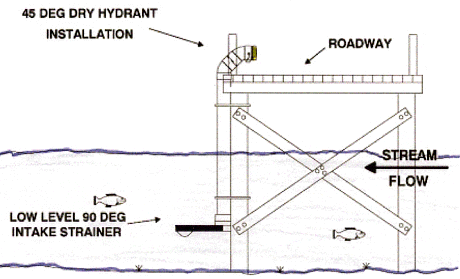
3. Supported vertically from the top (rigid installation)
This design uses a supporting structure such as a bridge or pier to maintain a given intake point below the surface. This design is intended for water supplies where the level is fairly stable year round. It does not provide any adjustment should the water level change.
As noted before Barrel Strainers or Low Level Strainers work very well in this application. Special large basket strainers can also be designed for this use.
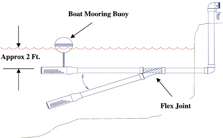
4. Suspended horizontally from the top using flotation buoys
This design uses a short section of flexible suction hose and a standard boat-mooring buoy. The 3 ft. flex hose assembly comes complete with; 6” Sched 40 PVC, Straight Pipe Connections on each end. The collars are the same as used on our standard suction hose and can be changed in the field, if needed. The horizontal strainer, as shown, works well in this application. Caution: If severe low water levels are encountered, it may be necessary to install legs on the strainer to assure at least 6-8 inches of clearance is always maintained between the strainer and pond bottom. Our horizontal strainer works well as long as the hole pattern is submerged.
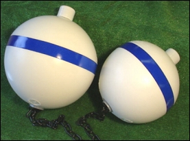
Mooring Buoys - Dry Hydrant Installation
Mooring buoys can be used for a variety of reasons. They are great to indicate the end of a strainer in busy waterways or can be used to support a suction hose or strainer when debris or silt is a concern. It may also be used with the "PVC Flex Joint" to maintain a constant suction depth for Dry Hydrant installations.
Buoys are hard skinned and almost indestructible. Buoys are made
from high-density polyethylene, filled with closed cell foam. White
with blue florescent stripe. Highly visible to navigation. All come
complete with 3 ft of heavy-duty 2" plastic chain. Available
in 12", 15" or 18" Diameters.
| Mooring Buoys | ||
|---|---|---|
| Assembly Number | Diameter | Buoyancy |
| 9769-612 | 12 Inches | 30 Lbs |
| 9769-615 | 15 Inches | 60 Lbs |
| 9769-618 | 18 Inches | 100 Lbs |
3 ft. PVC/Flex Joint as purchased.
(click on image for larger view)
|
|
Flex Assembly with PVC Ends. |
End view with collar. |
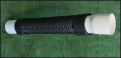
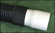
| Part No. | Size | Description |
|---|---|---|
| 9681-000 | 6" | PVC/Flex Joint Assembly |
5. Buried intake in a Sand or Gravel Bed
Placing an intake into the ground may seem like a crazy idea but if done properly, can provide a clean abundant water supply. This idea has been used in sandy soils with high water tables for many years. Many Golf Courses get their water from long buried pipes which lay buried horizontally in the ground.
Dry Hydrant Design Solutions Menu |
|
|---|---|